MAX2160 ISDB-T Reference Design
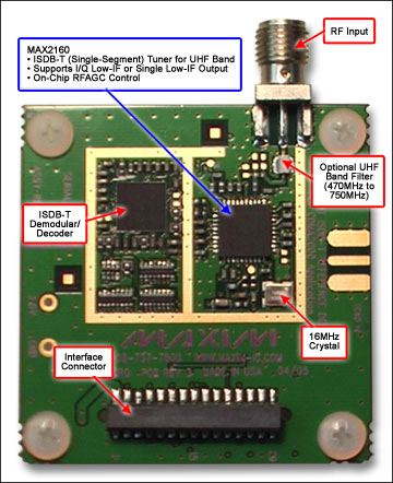
Figure 1. The reference design for the MAX2160 tuner plus demodulator.
Figure 2. System block diagram.
详情介绍

Click here for an overview of the wireless components used in a typical radio transceiver.
Figure 1. The reference design for the MAX2160 tuner plus demodulator.
Figure 2. System block diagram.
Lab Measurements

Figure 3. Sensitivity measures better than -97dBm.
The tradeoff in sensitivity is also shown when an optional WCDMA or cdma2000® rejection filter is added at the RF input.
Figure 4. A WCDMA blocker rejection filter response.
To implement on-board coexistence of ISDB-T with a WCDMA system, additional input filtering is required to reject the cellular transmit-band frequencies. The optional reference-design filtering is a combination of two filters, which provide approximately 47dB of attenuation at the cellular transmit band (marker 4).
Figure 5. CDMA-2000 blocker rejection filter response.
To implement on-board coexistence of ISDB-T with a cdma2000 system in a handheld application, additional input filtering is required to reject the cellular transmit-band frequencies. The optional reference-design filter provides approximately 42dB of attenuation at cdma2000 transmit frequencies (marker 4).
Additional Measurements
| Parameter | Conditions | Target | Measured | Units |
|---|---|---|---|---|
| Maximum Input | UHF: Ch. 13, Ch. 33, Ch. 52 | 0 | 8.9, 8.2, 7.3 | dBm |
| Adjacent Channel Selectivity (Desired: -70dBm) |
UHF: Ch. 13, Ch. 33, Ch. 52 | 35 | 45, 47, 45 | dBc |
| WCDMA Blocker Performance | UHF: Ch. 13, Ch. 33, Ch. 52 | 24 | 23.5, 24, 24 | dBm |
| cdma2000 Blocker Performance | UHF: Ch. 13, Ch. 33, Ch. 52 | 10 | 21, 21, 21 | dBm |
ISDB-T Frequency Plan
Figure 6. The ISDB-T RF signal is broadcast in the UHF band, as shown above. The channel spacing is 6MHz.
Detailed Description
The MAX2160/MAX2160EGB tuner ICs are designed for use in Japanese mobile digital-TV (ISDB-T single-segment) applications. The devices directly convert UHF band signals to a low-IF by using a broadband I/Q downconverter. The operating frequency range extends from 470MHz to 770MHz.
The MAX2160/MAX2160EBG support both I/Q low-IF interfaces and single low-IF interfaces. The devices are thus universal tuners for various digital demodulator implementations.
The MAX2160/MAX2160EBG integrate LNA, RF and low-IF variable-gain amplifiers (VGAs), I and Q downconverting mixers, and bandpass filters providing in excess of 42dB of image rejection. The parts operate with either high-side or low-side local oscillator (LO) injection. The devices' VGAs provide in excess of 100dB of gain-control range.
The MAX2160/MAX2160EBG also have fully monolithic VCOs and tank circuits, and a complete frequency synthesizer. A XTAL oscillator and separate TCXO input buffer are also included. The devices operate with XTAL/TCXO oscillators from 13MHz to 26MHz, which enable the shared use of a VC-TCXO in cellular handset applications. Additionally, a divider is provided for the XTAL/TCXO oscillator, thus allowing for a simple and low-cost interface to various channel decoders.