GPS USB Reference Design with the MAX2769
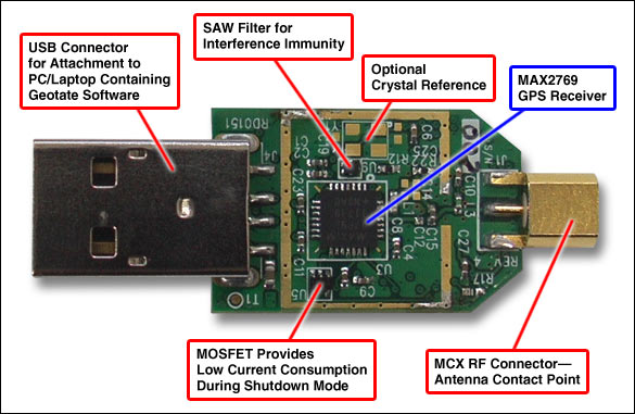
Figure 1. Top view of the GPS reference design that features the MAX2769 universal GPS receiver.
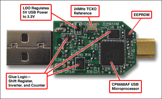
Figure 2. Bottom view of the design board.
Important Design Features
- Complete USB Solution When Paired with Geotate Software
- MAX2769 Offers 1.4dB Cascaded Noise Figure, and 115dB Gain with 60dB AGC Range
- Receiver/Software Combination Provides -139dBm Acquisition Sensitivity and -152dBm Tracking Sensitivity
- Choice of Two LNAs for Use with Active or Passive Antenna
- Choice of Single or Dual Frequency References
- Fractional-N Synthesizer and Wide Range of IF Filters for Maximum Flexibility
- SAW Filter for Noise Immunity
详情介绍
Figure 1. Top view of the GPS reference design that features the MAX2769 universal GPS receiver.
Figure 2. Bottom view of the design board.
Important Design Features
- Complete USB Solution When Paired with Geotate Software
- MAX2769 Offers 1.4dB Cascaded Noise Figure, and 115dB Gain with 60dB AGC Range
- Receiver/Software Combination Provides -139dBm Acquisition Sensitivity and -152dBm Tracking Sensitivity
- Choice of Two LNAs for Use with Active or Passive Antenna
- Choice of Single or Dual Frequency References
- Fractional-N Synthesizer and Wide Range of IF Filters for Maximum Flexibility
- SAW Filter for Noise Immunity
Figure 3. Block diagram of the GPS USB reference design.
Lab Measurements
|
Figure 4. Data shows time to first fix under cold-start conditions. At high levels, the average fix time is 30 seconds. At 2dB above sensitivity level, the fix time is around 50 seconds. The sensitivity level is defined as that incident power where fix time exceeds 150 seconds.
Detailed Description
The MAX2769 offers a choice of two different integrated LNAs. LNA1 has a higher gain and a lower noise figure for use with a passive antenna; LNA2 offers a higher IP3 and lower power consumption at the expense of a slightly lower gain and higher noise figure. LNA2 is for use with active external antennas. The pin-out allows for an external GPS-band filter between the LNA output and the mixer input. Both the reference and IF frequencies are variable and can match a broad variety of frequency plans. The I and Q channel-select filters cover a wide range of bandwidths, and can be selected as either third or fifth order. In this way, the baseband processor can adjust (or fix) the desired channel bandwidth for best sensitivity. An on-chip fractional-N synthesizer, tuned with the help of an external loop filter, provides high-IF selectivity with low phase noise. The IF output is adjustable in 63 steps between 0MHz and 12.5MHz. The integrated ADCs can be set to 1-, 2-, or 3-bit resolution.
This reference design utilizes 1-bit data and downconverts the L1 band 1575.42GHz GPS (or Galileo) signal to a 1.57MHz IF. A USB microprocessor and glue logic provide a full USB interface with a PC or laptop. The design operates with Geotate's "Spot" software installed on the PC's CPU. While the design is delivered with a single TCXO reference of 24MHz, it can operate with separate references for the digital and RF portions, thus permitting the use of a different RF reference, if desired. Customers could select between the two LNAs with a change of software version and the replacement of one capacitor on the board. A SAW filter is included after the LNA for noise immunity. The system could also be retuned for GLONASS operation by replacing the SAW filter and changing a software version. The SPI information required to set up the IC is delivered over the USB lines and converted in the microprocessor to the 3-signal format that the IC requires. PID/VID information, along with the necessary information to program the settings upon startup, is loaded through an EEPROM on the board.
Glue logic is used both to convert the serial data output from the IC to parallel format for the microprocessor, and to adjust clock timing. The microprocessor then converts the information to DP and DM signals for transmission over the USB cable to the PC processor. At that point the Spot software converts the signals into latitude, longitude, and altitude information. Spot software enables the user to observe satellite and signal-strength information, almanac information, time to first fix, and position information.
| Application Note Links |
Application note 3910, "A User Guide for the MAX2769 GPS Receiver."