Simple Wireless Temperature Monitor Also Has Data-Logging Capabilities
You can design a simple wireless temperature-monitoring system with data-logging capabilities by using a local temperature sensor and an ASK transmitter (Figure 1) and receiver pair. A MAXQ® microcontroller processes and displays the temperature reading to the user (Figure 2). The microcontroller's onboard UARTalso allows for data-logging applications.
In Figure 1, the MAX6577 is a local temperature sensor that detects the ambient temperature at the device. The output of the MAX6577 is a square wave with a frequency proportional to temperature in units of Kelvin. The MAX1472 is the ASK transmitter and modulates the signal on to the carrier frequency of 315MHz.
In Figure 2, the MAX1470 is the ASK receiver and demodulates the signal at the corresponding carrier frequency. The output signal's frequency is measured with a frequency counter. The configured scalar multiplier is 1K/Hz when TS1 is connected to GND and TS0 connected to VDD. This scalar multiplier is configurable with pins TS1 and TS0 (Figure 1).
The MAX9075 is a comparator connected to the MAX1470's RSSI with internal peak detector pin. The external RC follows the peak power of the received signal. This is compared with a predetermined voltage level generated by a resistor voltage divider. Lab experiments show that a threshold of approximately 1.57V generates a valid output on the DATAOUT pin without receiving false readings. Adjust this threshold to the proper level for optimal performance. The comparator's output is low when a weak or invalid signal is received and high when the received signal is adequate.
Next the MAXQ2000, a MAXQ-based microcontroller, measures the signal frequency and displays the value using its integrated timer/counters and LCD driver peripherals. A counter tracks the number of rising-edge transitions on the input temperature signal, while a timer tracks the elapsed time. After the timer's 1-second period elapses, an interrupt occurs. At this moment, the counter value is read, converted to Celsius, and displayed on the LCD. Next, the counter is reset to 0 to restart the process. The timer is automatically reloaded once the timer interrupt occurs. The resulting temperature is also output by UART0. A handheld frequency counter is used to verify the temperature reading.
The microcontroller monitors the signal power through P6.0, configured as a general-purpose input pin. When the input is logic low, the LCD and UART output will be "no RF" to alert the user of possible transmitter issues when the transmitter and receiver pair is separated by too great a distance.
The LCD connection follows the design in the MAX2000 evaluation (EV) kit. To ensure that the display enables the correct segments, the internal mapping of the display's seven A-to-G segments needs to be preserved. A lookup table in the data segment of the assembly code is used for this purpose. By adding an RS-232 level converter, the UART output can send data to a data-logging device such as a computer.
The MAX-IDE assembler software is used to program the device during assembly. The MAXQJTAG board operates with the MAX-IDE to load the code onto the device. The project files associated with this article are available for download.
详情介绍

Click here for an overview of the wireless components used in a typical radio transceiver.
You can design a simple wireless temperature-monitoring system with data-logging capabilities by using a local temperature sensor and an ASK transmitter (Figure 1) and receiver pair. A MAXQ® microcontroller processes and displays the temperature reading to the user (Figure 2). The microcontroller's onboard UARTalso allows for data-logging applications.
In Figure 1, the MAX6577 is a local temperature sensor that detects the ambient temperature at the device. The output of the MAX6577 is a square wave with a frequency proportional to temperature in units of Kelvin. The MAX1472 is the ASK transmitter and modulates the signal on to the carrier frequency of 315MHz.
In Figure 2, the MAX1470 is the ASK receiver and demodulates the signal at the corresponding carrier frequency. The output signal's frequency is measured with a frequency counter. The configured scalar multiplier is 1K/Hz when TS1 is connected to GND and TS0 connected to VDD. This scalar multiplier is configurable with pins TS1 and TS0 (Figure 1).
The MAX9075 is a comparator connected to the MAX1470's RSSI with internal peak detector pin. The external RC follows the peak power of the received signal. This is compared with a predetermined voltage level generated by a resistor voltage divider. Lab experiments show that a threshold of approximately 1.57V generates a valid output on the DATAOUT pin without receiving false readings. Adjust this threshold to the proper level for optimal performance. The comparator's output is low when a weak or invalid signal is received and high when the received signal is adequate.
Next the MAXQ2000, a MAXQ-based microcontroller, measures the signal frequency and displays the value using its integrated timer/counters and LCD driver peripherals. A counter tracks the number of rising-edge transitions on the input temperature signal, while a timer tracks the elapsed time. After the timer's 1-second period elapses, an interrupt occurs. At this moment, the counter value is read, converted to Celsius, and displayed on the LCD. Next, the counter is reset to 0 to restart the process. The timer is automatically reloaded once the timer interrupt occurs. The resulting temperature is also output by UART0. A handheld frequency counter is used to verify the temperature reading.
The microcontroller monitors the signal power through P6.0, configured as a general-purpose input pin. When the input is logic low, the LCD and UART output will be "no RF" to alert the user of possible transmitter issues when the transmitter and receiver pair is separated by too great a distance.
The LCD connection follows the design in the MAX2000 evaluation (EV) kit. To ensure that the display enables the correct segments, the internal mapping of the display's seven A-to-G segments needs to be preserved. A lookup table in the data segment of the assembly code is used for this purpose. By adding an RS-232 level converter, the UART output can send data to a data-logging device such as a computer.
The MAX-IDE assembler software is used to program the device during assembly. The MAXQJTAG board operates with the MAX-IDE to load the code onto the device. The project files associated with this article are available for download.
This design provides for 1-second temperature refresh rate in 1°C increments, which is within the accuracy of the MAX6577.
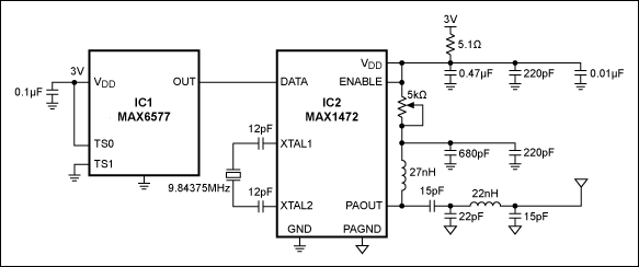
Figure 1. The MAX6577 temperature sensor and the MAX1472 315MHz ASK transmitter form a wireless temperature-monitoring system.
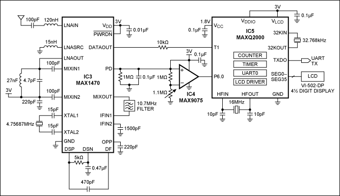
Figure 2. The MAX1470 ASK receiver with a MAXQ microcontroller processes and displays temperature data.
MAXQ is a registered trademark of Maxim Integrated Products, Inc.