FREMONT (MAXREFDES6#):16位、高精度、0至100mV输入、隔离型模拟前端(AFE)

概述
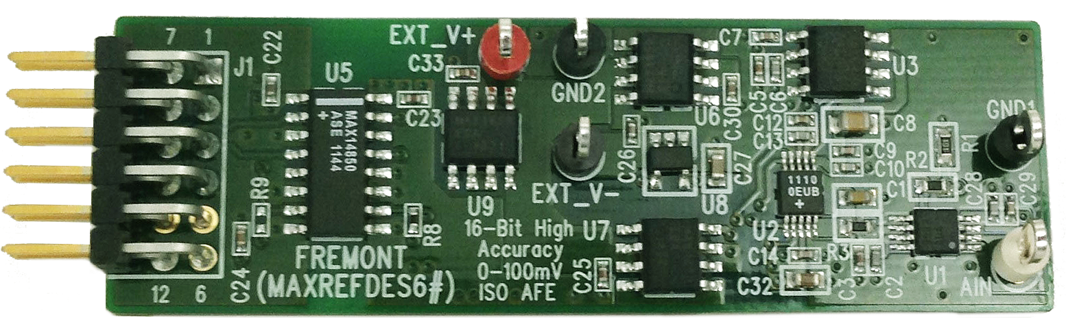
紧凑的Fremont (MAXREFDES6#)子系统参考设计(图1)利用高精度、16位模拟前端(AFE)准确测量0至100mV低压单端模拟信号,并配备隔离数据通路。设计充分利用以下器件的功能:超高精度、低噪声缓冲器(MAX9632);高精度ADC (MAX11100);超高精度4.096V电压基准(MAX6126);600VRMS单芯片数据隔离器(MAX14850);低压差(LDO)稳压器,提供稳压+6V、+5V和-5V电源(MAX1659和MAX1735)。这种独一无二的AFE方案非常适用于要求低电压输入、高阻抗以及高精度模/数转换的众多应用。智能工厂、工业以及医疗应用使用的传感器越来越多,配置各异。尽管低压传感器提供关键数据,但它们也要求/产生高信噪比信号,致使许多分立式和集成式模/数转换器(ADC)不足以满足此类应用。

图1. Fremont子系统设计方框图。
特性 |
应用 |
|
|
竞争优势
- 独特的单端结构
- 最优的电路板尺寸
- 抗磁干扰数据通路隔离
详情介绍
Introduction
 More detailed image (JPG) |
Smart factories, industrial, and medical applications continue to utilize more sensors, of various configurations. While low-voltage sensors provide essential data, they also require/generate high signal-to-noise ratios, rendering many discrete and integrated analog-to-digital converters (ADCs) insufficient for these applications.
The compact Fremont (MAXREFDES6#) subsystem reference design (Figure 1) accurately measures low voltage, 0 to 100mV, single-ended analog signals with a high-accuracy, 16-bit analog front end (AFE) complete with an isolated data path. The design optimizes the functions of an ultra-precision low-noise buffer (MAX9632); a highly accurate ADC (MAX11100); an ultra-high-precision 4.096V voltage reference (MAX6126); a 600VRMS monolithic data isolator (MAX14850); and low-dropout (LDO) regulators providing regulated +6V, +5V, and -5V power rails (MAX1659 and MAX1735). This oneofakind AFE solution works in many applications requiring low-voltage input, high impedance, and high-accuracy analog-to-digital conversion.
Figure 1. The Fremont subsystem design block diagram.
Features |
Applications |
|
|
Competitive Advantages
- Unique single-ended architecture
- Optimized board size
- Magnetically immune data path isolation
Detailed Description of Hardware

Fremont interfaces with field-programmable gate array (FPGA) development boards using a Pmod connector. The Pmod specification allows for both 3.3V and 5V modules as well as various pin assignments. Fremont requires a 3.3V supply voltage and uses the SPI pin assignments as illustrated here.
Table 1 shows the power requirements. Table 2 shows the supported platforms and ports.
Table 1. Power Requirement for the Fremont Subsystem Reference Design
| Power Type | Input | Input Voltage (V) | Input Current (mA, typ) |
|---|---|---|---|
| External Power | EXT_V+ | 7 | 22 |
| External Power | EXT_V- | -6 | 20 |
Table 2. Supported Platforms and Ports
| Supported Platforms | Ports |
|---|---|
| Nexys™ 3 platform (Spartan®-6) | JB1 |
| ZedBoard™ platform (Zynq®-7020) | JA1 |
The MAX9632 (U1) op amp input circuit amplifies and buffers a 0 to100mV signal to match the input range of the ADC (MAX11100), which is 0 to 4.096V.
The MAX11100 (U2) is a 16-bit, successive-approximation register (SAR) ADC with AutoShutdown™ and fast 1.1µs wake-up features. The ADC’s reference input is driven by an ultra-high-precision 4.096V voltage reference, the MAX6126 (U3), with 0.02% initial accuracy and a 3ppm/°C maximum temperature coefficient (tempco).
The Fremont hardware design provides isolated data (MAX14850) for a high-accuracy, high-impedance, 0 to 100mV signal, analog-to-digital conversion application.
External power supplies power the Fremont board prior to voltage regulation. The MAX1659 LDO regulator provides +6V and +5V rails and the MAX1735 LDO regulator provides the -5V rail. The MAX14850 (U5) isolates the digital data up to 600V.
To power the Fremont board, connect the ground terminal of the external power supplies to the GND2 connector. Connect the +7V to +16.5V supply to the EXT_V+ connector, and the -6V supply to the EXT_V- connector.
Detailed Description of Firmware for Nexys 3 Platform
Table 2 shows currently supported platforms and ports. Support for additional platforms may be added periodically under Firmware Files in the All Design Files section below.
The Fremont firmware released for the Nexys 3 development kit targets a Microblaze™ soft-core microcontroller placed inside a Xilinx® Spartan-6 FPGA.
The firmware allows for immediate interfacing to the hardware, and for collection and saving of samples. Figure 2a shows the simple process flow. The firmware is in C, developed using the Xilinx software development kit (SDK) tool, based on the Eclipse™ open source standard. Custom Fremont-specific design functions (driver in the maximDeviceSpecificUtilities.c file) were created utilizing the standard Xilinx XSpi core version 3.03a. The SPI clock frequency is set to 3.125MHz.

Figure 2a. The Fremont firmware flowchart for Nexys 3 platform.
The firmware accepts commands, writes status, and can download blocks of sampled data to a standard terminal program over a virtual COM port. The complete source code speeds customer development. Code documentation resides in the corresponding firmware platform files.
Detailed Description of Firmware for ZedBoard Platform
The Fremont firmware design also supports the ZedBoard kit and targets an ARM® Cortex® -A9 processor placed inside a Xilinx Zynq system-on-chip (SoC).
The firmware features an AXI MAX11100 custom IP core to optimize the sampling rate and SPI timing stability.
The firmware allows for immediate interfacing to the hardware, for collection and saving of samples. Figure 2b shows the simple process flow. The firmware is in C, developed using the Xilinx SDK tool, based on the Eclipse™ open source standard. Custom Fremont-specific design functions (driver in the maximDeviceSpecificUtilities.c file) were created utilizing the AXI MAX11100 custom IP core. The SPI clock frequency is 4.54MHz when the sample rate is 189.4ksps. The SPI clock frequency is set to 2.5MHz for all other sampling rate.

Figure 2b. The Fremont firmware flowchart ZedBoard platform.
The firmware accepts commands, writes status, and can download blocks of sampled data to a standard terminal program over a virtual COM port. The complete source code speeds customer development. Code documentation resides in the corresponding firmware platform files.
Quick Start
Required equipment:
- Windows® PC with two USB ports
- Fremont (MAXREFDES6#) board
- Fremont-supported platform (i.e., Nexys 3 development kit or ZedBoard kit)
- Industrial sensor or signal source
Download, read, and carefully follow each step in the appropriate Fremont Quick Start Guide:
Fremont (MAXREFDES6#) Nexys 3 Quick Start Guide
Fremont (MAXREFDES6#) ZedBoard Quick Start Guide
Lab Measurements
Equipment:
- HP 33120A waveform generator
- Voltage calibrator DVC-8500
- Windows PC with two USB ports
- Fremont (MAXREFDES6#) board
- Nexys 3 development kit
- +7V power supply
- -6V power supply
Take special care and use proper equipment when testing the Fremont design. Any high-accuracy design requires sources and measurement equipment of higher accuracy than the design under test. Duplication of the presented test data requires a low distortion signal source. A HP 33120A function generator produced the input signal, and the FFTs were created using the FFT control in SignalLab from Mitov Software.
Figure 3 and Figure 4 show AC and DC performance.

Figure 3. AC FFT using on-board isolated power, a 0 to 100mV, 1kHz sine-wave input signal, high-impedance input, a 20ksps sample rate, and a Blackman-Harris window.

Figure 4. DC histogram using on-board isolated power; a 50mV input signal; a 20ksps sample rate; 65,536 samples; a code spread of 19 LSBs with 95.7% of the codes falling within the nine center LSBs; and a standard deviation of 2.236.
ARM is a registered trademark and registered service mark of ARM Limited.
![]() AutoShutdown is a trademark of Maxim Integrated Products, Inc.
AutoShutdown is a trademark of Maxim Integrated Products, Inc.
![]() Cortex is a registered trademark of ARM Limited.
Cortex is a registered trademark of ARM Limited. ![]()
Eclipse is a trademark of Eclipse Foundation, Inc.
![]() MicroBlaze is a trademark of Xilinx, Inc.
MicroBlaze is a trademark of Xilinx, Inc.
![]() Nexys is a trademark of Digilent Inc.
Nexys is a trademark of Digilent Inc.
![]() Pmod is a trademark of Digilent Inc.
Pmod is a trademark of Digilent Inc.
![]() Spartan is a registered trademark of Xilinx, Inc.
Spartan is a registered trademark of Xilinx, Inc.![]()
Windows is a registered trademark and registered service mark of Microsoft Corporation.![]()
Xilinx is a registered trademark and registered service mark of Xilinx, Inc.![]()
ZedBoard is a trademark of ZedBoard.org.![]()
Zynq is a registered trademark of Xilinx, Inc.