MAXREFDES72#:适用于ARDUINO平台的PMOD适配器

“标准的奇妙之处在于众多的选择。” 格蕾丝·赫柏 (Grace Hopper)1
概述
多年以来,一直存在标准泛滥的现象,而我们电子业尤其严重。您是否很好奇为什么有的标准最终变成古怪的数字,看起来好像与逻辑测量单位毫无关系?关于航天飞机的固体燃料火箭推进器的直径是否真的源自于马屁股的宽度的讨论非常激烈。2相当的稀奇和有趣。但是,接受事实会更有成效:总是会有很多标准,我们必须找到使其很好配合的途径。工程师和制造商均涉及到一个共同领域:原型平台,其中标准的不兼容特别麻烦。庆幸的是,MAXREFDES72#参考设计能够缓解这种不兼容问题。
特性
- 兼容Arduino® UNO R3
- IOREF支持3.3V或5V信号电平
- 2x6 Digilent® Pmod™兼容接口
- 支持1、2、3和4型Pmod,以及I2C和非标准引脚排列
- Pmod和Arduino引脚之间电平转换
- 高精度RTC,带有集成MEMS谐振器
应用
- 原型设计
- 科展项目
- 制造商和业余爱好者项目
- 科学和电子教育
- 模拟外设测试和集成
详情介绍
 放大+
放大+
“The wonderful thing about standards is that there are so many of them to choose from.” Grace Hopper1
Introduction
Through the years there has been a proliferation of standards, and not many industries have created more than our electronics industry. Do you ever wonder why certain standards end up as odd numbers, seemingly unrelated to a logical unit of measurement? The debate rages on over whether or not the standard that determined the diameter of the solid rocket boosters for the space shuttle actually originated from the back side of a horse.2 Curious and interesting, yes. But, we are certainly more productive by accepting the fact that there will always be many standards and finding ways to make them play well together. There is one specific area for both engineers and makers, where the incompatibility of standards is particularly troublesome: prototyping platforms. Fortunately, the MAXREFDES72# reference design is available to mitigate these incompatibilities.
Features
- Arduino® UNO R3 compatible
- IOREF support for 3.3V or 5V signal levels
- 2x6 Digilent® Pmod™ compatible interface
- Supports Pmod types 1, 2, 3, and 4, I2C and nonstandard pinouts
- Level shifting between Pmod and Arduino pins
- Precision RTC with integrated MEMS resonator
Applications
- Prototyping
- Science fair projects
- Maker and hobbyist projects
- Science and electronics education
- Analog peripheral testing and integration
Detailed Circuit Description
MAXREFDES72# consists of the MAX14661 Beyond-the-Rails™ 16:2 multiplexer, two MAX14611 level shifters, and the DS3231M real-time clock. The system block diagram is shown in Figure 1. Prior to describing the details of the system hardware, this article will provide an overview of the various pinouts associated with Pmod connectors and Arduino interfaces
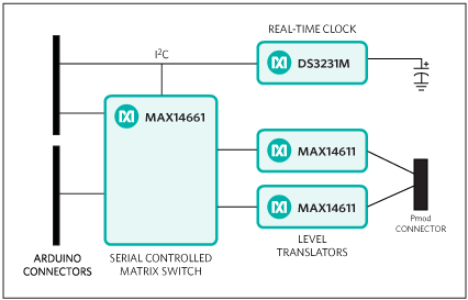
Figure 1. The MAXREFDES72# system block diagram.
Development Board Expansion Standards
For years component manufacturers have offered development systems to assist their customers with designing applications around their parts. For programmable devices such as FPGAs and microcontrollers, there are always connections for interfacing to the other components so that software development can begin along with, or before, the hardware. With time, very loose pseudo standards for these “expansion interfaces” have emerged, some more consistent than others. FPGA vendors, such as Xilinx®, have driven some of these standards like FMC to make it as easy as possible for customers to migrate to the newest platform. Xilinx has also used third-party standards like the Pmod standard developed by Digilent, allowing Xilinx to leverage the wide selection of peripherals for this interface.3 Microcontroller manufacturers have been somewhat slower to standardize, many utilizing their own proprietary interfaces. However, market forces like the maker movement and the popularity of the Arduino platform are herding them towards pseudo standards too.
Pmod Is Well-Suited for FPGAs
The Pmod interface is a great way to mix and match peripherals with an FPGA development board. It provides access to eight pins plus power and ground in a convenient, hand-solderable connector. The flexibility of FPGAs allows the eight signal pins to be used for almost anything. While this flexibility enhances the utility for FPGAs, it also makes the interface difficult to use with microcontrollers whose peripherals are assigned to specific pins. To address this problem, Digilent defined several different Pmod pinout types with various functions assigned to specific pins (Figure 2).

Figure 2. Pmod pinout types have various functions assigned to specific pins.
The type definitions make it easier to use the Pmod interface standard with a microcontroller board, but there are still challenges. The deprecated Type 3 UART interface is a good example of the difficulties involved with implementing a truly universal interface with the limited pin-muxing capabilities of many microcontrollers. Nonetheless, even with its limitations, the Pmod interface is a very useful expansion port for prototyping or educational endeavors.
| Pin | I2C | Type 1 GPIO | Type 2 SPI | Type 3 UART | Type 4 UART | Type 5 H-Bridge | Type 6 Dual H-Bridge | |
| A1 | 1 | IO1 | SS | CTS | CTS | DIR | DIR1 | |
| A2 | 2 | IO2 | MOSI | RTS | TXD | EN | EN1 | |
| A3 | 3 | SCL | IO3 | MISO | RXD | RXD | SA | DIR2 |
| A4 | 4 | SDA | IO4 | SCK | TXD | RTS | SB | EN2 |
| A5 | 5 | GND | GND | GND | GND | GND | GND | GND |
| A6 | 6 | VCC | VCC | VCC | VCC | VCC | VCC | VCC |
| B1 | 7 | INT | INT | |||||
| B2 | 8 | RESET | RESET | |||||
| B3 | 9 | SCL | N/S | N/S | ||||
| B4 | 10 | SDA | N/S | N/S | ||||
| B5 | 11 | GND | GND | GND | GND | GND | GND | GND |
| B6 | 12 | VCC | VCC | VCC | VCC | VCC | VCC | VCC |
The Arduino Pseudo Standard
The Arduino pseudo standard is a completely different beast, a different platform developed for a different audience, for different reasons. The original Arduino board simply exposed the pins of a simple microcontroller and added enough supporting devices to make it easy to program, yet still affordable for hobbyists. Because of its simple nature, the original pinout was defined by the capabilities of the microcontroller.
As the platform evolved to support more-capable processors, this pseudo standard was fragmented with a myriad of pin-muxing combinations with, arguably, more exceptions than rules. Some issues, such as support for different I/O voltages and the inconsistency of I2C signals, were addressed in revision 3 of the UNO board. Yet, anyone pairing an Arduino board (or any of the Arduino derivatives) with a shield still needs to carefully review the compatibility. And, there is no shortage of Arduino derivatives to choose among (Figure 3). Even if limited to the official boards at the Arduino website, pin compatibility is far from trivial. But, in general, each Arduino pin has a special function and can also be used as a general-purpose I/O (GPIO).

Figure 3. Arduino footprint boards are configured in many derivatives to support different designs and applications.
Unlike the Pmod interface, where a pin can serve several special functions, most Arduino pins typically perform a single special function. As would be expected from its roots, the Arduino pseudo specification is better suited for microcontrollers than the Pmod interface. This is, consequently, a major reason why it is so much easier to find microcontroller boards in the Arduino form factor than with Pmod connectors.
Mapping Between the Pmod and Arduino Interfaces
So we have the Pmod interface and the Arduino pseudo standard, both readily available from numerous sources. Is there any hope of getting a peripheral from one platform to communicate with a controller from the other? Of course anything is possible, but sometimes the cure is worse than the disease.
If the Arduino UNO rev 3 pinout is compared to the Pmod specification, you immediately see that there are 22 signal pins on the Arduino board and only eight on the Pmod connector. It is technically possible to serialize all 22 pins and pass them through the eight pins provided by the Pmod and then deserialize them on the other side, but that effort will be left as an exercise for the reader. The task of adaptively mapping the 22 Arduino signals into the different types defined in the Pmod specification (Figure 2) is more manageable, yet still not trivial. Figure 2 above shows the pinouts for five different Pmod types. Many of the signals are level sensitive and can be controlled through software by a GPIO pin. However, some of the signals utilize time-sensitive protocols that are easier to work with by utilizing the peripherals inside the microcontroller. The challenge, therefore, is getting all the dedicated pins of the microcontroller to the pin designated in the Pmod specification.
Proposed Solution: Use a Serial-Controlled Crosspoint Switch
One way to address this mapping problem is to put an array of configuration jumpers on the board. While straightforward, this is certainly neither elegant nor user friendly. The font size required to fit the instructions on an Arduino-sized board would be illegible. Many of the pins can be bidirectional, so simple logic gates are not an option for signal routing. Analog switches would work, but there are not enough extra pins to control them individually. The pin shortage could be addressed with I2C port expanders. Granted, that tactic would not be much more elegant than the jumpers, but it would be software configurable.
This endeavor would seem hopeless were it not for a serial-controlled 16:2 multiplexer, the MAX14661. At first glance, one might think that four of these devices are required to support all the different Pmod types. Such an approach would hardly seem much better than the port expander solution. That would be true, except…the MAX14661 features a special capability. It allows for any combination of switches to be active at once, so it can be used as an 8:8 crosspoint switch.
So far, so good. But there is, admittedly, a limitation to the 8:8 crosspoint configuration: it can only pass two independent signals simultaneously, one for each COM_ pin. But what good are two simultaneous signals? As stated before, most signals can be driven by GPIOs and there are only a few signals that require the internal peripheral controllers. If one GPIO is assigned to each pin, only the time-sensitive serial lines need to be routed through the mux. A UART and I2C are each two-wire buses, so the only serial interface that does not fit through the mux is SPI. There is only one interface defined for SPI, therefore, the SPI signals are routed directly to the connector and used as the GPIO connections for those pins. When one of those pins is needed for a time-sensitive function, simply tristate the GPIO.
What about signal-voltage levels? The original Arduino design and many of its successors used 5V signal levels, but 5V signaling is not as common as it used to be. To address this, an IOREF pin was added to later Arduino boards to indicate the signal level for derivatives based on lower-voltage microcontrollers. The Pmod connector does not have an IOREF pin, but the vast majority of its modules support 3.3V signaling. Fortunately, bidirectional level shifters like the MAX14611 address this issue. Simply connect the Arduino signals to one side of the level shifter powered by IOREF. Then connect the other side to the Pmod connector powered by the dedicated 3.3V supply from the Arduino board. The MAX14661 mux can tolerate and pass any signal from -5V to +5V with any supply between 1.8V and 5V, so it can be located on either side of the level shifter. Since there are more Arduino connections to the mux than Pmod connections, it makes sense to put the MAX14661 on the Arduino side of the level shifters. In that way only two of the 4-channel devices are needed at the Pmod connector (Figure 4).

Figure 4. Logical Diagram of proposed solution.
Evaluating this Solution
The key to this solution is that each channel supports multiple simultaneous connections. The COM_ pins are not connected, but are used internal to the mux for routing. Eight of the MAX14661’s 16 mux connections are dedicated to the Pmod connector, which is also connected to the four SPI-capable signals and four other GPIOs (Figure 4). The other eight mux connections are connected to the 2-wire serial buses and other time-critical signals like PWM or timer pins. To implement the I2C type, for example, simply configure the mux so that the SDA pin and Pmod pin 4 are enabled on channel A, and SCL and Pmod pin 3 are enabled on channel B. Channels A and B are arbitrary and can be swapped freely. In fact, one could even enable pins 3 and 4 on the second row of the Pmod connector to access a second 6-pin I2C Pmod. You can even leave both ports active if the I2C devices have different addresses, or dynamically activate them to support two devices with the same address. Dynamically switching between two devices with the same address is simply not possible using jumpers. Using the MAX14661 it is possible to programmatically configure all the specified Pmod types and even some nonstandard types with a single active device that is only 4mm x 4mm.
Why would anyone design a nonstandard Pmod? One reason is the same pin-muxing problem found with microcontrollers. For example, devices like the MAX3107 support both I2C and SPI interfaces, but the pins are not shared in the same pin mapping used on the standard Pmod types. With the MAX14661 this is not a problem because the programmability allows for connecting the I2C signals to any pin. The Arduino boards provide yet another example of the value of this programmability with their UART connections. Pins D0 and D1 connect to both the microcontroller and the on-board USB virtual com port. The MAX14661 provides the ability to swap the polarity of D0 and D1 so that the peripheral module can connect to either the microcontroller or the virtual com port.
When you use the MAX14661 to multiplex I2C buses, the commands are sent in-band. The switching will take effect synchronously with the I2C bus. It can, admittedly, be challenging to multiplex I2C buses out-of-band because, if care is not taken, you can disconnect while a slave is holding the SDA line low. The next time you select that branch of the bus, it might lock up. The MAX14661 will always transition the bus at the end of an I2C write command when the devices on the other side of the switch should be idle.
The DS3231M is a highly accurate real-time clock with an MEMS resonator. Within the MAXREFDES72#, the DS3231M serves to timestamp activity and communication. A community developed example of a DS3231 driver may be found at http://mbed.org/users/cromda/code/DS3231/. A Panasonic BR-1225 (not included) battery is required to maintain time when system power is disconnected.
Quick Start
Required equipment:
- Device with a modern web browser and the ability to write to an external USB drive
- Microcontroller board with Arduino UNO R3 compatible socket headers
- ARD2PMD (MAXREFDES72#) board
- MAX3232PMB1 or other Pmod-compatible peripheral module
Download, read, and carefully follow each step in the appropriate MAXREFDES72# Quick Start Guide.
Detailed Description of Firmware
Example firmware is in the MAXREFDES72# Quick Start guide. The firmware includes the library for the MAX14661, in the MAX14661.h file. A basic demonstration program is provided with step-by-step instructions for configuring the board to route UART signals from an Arduino compatible board to the MAX3232PMB1 using the mbed platform.
References
- See Simson Garfinkel, Daniel Weise, and Steven Strassmann, eds., The UNIX-HATERS Handbook, IDG Books Worldwide, Inc. An International Data Group Company, 1994, page 49.
- See “The Space Shuttle and the Horse’s Rear End”.
- See application note 5468, “Maxim Analog Essentials Collection”.
MAXREFDES72# is not connected to Arduino and is a derivative product.
All technical support requests must be directed to Maxim Integrated.
Arduino is a registered trademark of Arduino, LLC.
Beyond the Rails is a trademark of Maxim Integrated Products, Inc.
Digilent is a registered trademark of Digilent, Inc.
Pmod is a trademark of Digilent, Inc.
Xilinx is a registered trademark and registered service mark of Xilinx Corp.