MAXREFDES75#


概述
电子秤被广范应用于重量测量行业中。从质量超轻的试剂到大型集装箱,称重都为从化学反应到商品管理的各种过程提供关键信息。所有现代化电子秤的关键元件都是模/数转换器。MAXREFDES75#将完整24位ADC集成至高性能系统,执行小信号(低至±25mV满幅)24位测量,同时产生高压传感器电源,从而生成与输入信号成比例的0至10V输出。
MAXREFDES75#参考设计的特性包括:
- 比例测量或与高精度电压基准进行比较测量
- 用户可编程传感器(负载单元)的失调和增益校准
- 用户可编程DAC的失调和增益校准
- 用户可编程电压输出范围映射
MAX11270
- 24位分辨率,64ksps
- 6nV/√Hz集成式可编程增益放大器(PGA),增益可高达128
MAX542
- 16位分辨率,无失码
- 高精度INL ±2 LSB(最大)
详情介绍
概述
电子秤被广范应用于重量测量行业中。从质量超轻的试剂到大型集装箱,称重都为从化学反应到商品管理的各种过程提供关键信息。所有现代化电子秤的关键元件都是模/数转换器。MAXREFDES75#将完整24位ADC集成至高性能系统,执行小信号(低至±25mV满幅)24位测量,同时产生高压传感器电源,从而生成与输入信号成比例的0至10V输出。
MAXREFDES75#参考设计的特性包括:
- 比例测量或与高精度电压基准进行比较测量
- 用户可编程传感器(负载单元)的失调和增益校准
- 用户可编程DAC的失调和增益校准
- 用户可编程电压输出范围映射
MAX11270
- 24位分辨率,64ksps
- 6nV/√Hz集成式可编程增益放大器(PGA),增益可高达128
MAX542
- 16位分辨率,无失码
- 高精度INL ±2 LSB(最大)
Detailed Description
Figure 1 shows the block diagram of the MAXREFDES75#.
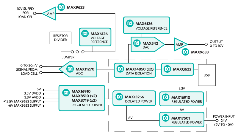
Figure 1. The MAXREFDES75# reference design block diagram.
The signal chain begins with the sensor signal feeding directly into the MAX11270. No external op amp is necessary because the PGA is integrated in the MAX11270. Following isolation via the MAX14850, the MAXQ622 reads the input signal, applies zero-offset and weight-factor, and presents the resulting weight. The MAXQ622 calculates a DAC value, based on DAC calibration and output range mapping and writes this to the DAC. A variety of sensor power options are available, outlined in Table 1.
Table 1. Sensor Supply Configuration
| ADC Input Configuration | Connectors | Shunt Positions |
|---|---|---|
| 10V generated on MAXREFDES75# | Output: S+ Bridge Output: S- Bridge Ratiometric setup Ratiometric setup |
JP5: horizontal JP6: horizontal JP2: 2-3 JP3: 2-3 |
| 3.3V generated on MAXREFDES75# | Output: S+ Bridge Output: S- Bridge Ratiometric setup Ratiometric setup |
JP5: vertical JP6: vertical JP2: 2-3 JP3: 2-3 |
| Sensor supplied externally ratiometric measurement | Input: S+ Bridge Input: S- Bridge Ratiometric setup Ratiometric setup |
JP5: open JP6: open JP2: 2-3 JP3: 2-3 |
| Sensor supplied externally use voltage reference | Input: S+ Bridge Input: S- Bridge Ratiometric setup Ratiometric setup |
JP5: open JP6: open JP2: 1-2 JP3: 1-2 |
Power Supply
The MAXREFDES75# is equipped with multiple sensor-supply options. Either 10V or 3.3V may be used to excite the load cell. Excitation at 10V will provide the highest performance, however, it will require additional components, and hence increase cost, in any final design. The 3.3V rail is required for ADC operation so it will be available in all configurations. Furthermore, the ADC may be configured to operate in a ratiometric mode, with the reference-derived resistor-divider from the 10V rail, or from the MAX6126 voltage reference. The ratiometric method is generally preferred, however, the voltage reference provides the user flexibility to evaluate the system without the changes in gain contributed by the system.
The MAXREFDES75# board receives power from a single DC source of 9V to 40V, 200mA through the X2 terminal block. The MAX17501 generates an +8V rail from the variable input supply. The MAX16910 LDO generates 3.3V for the MAXQ622 from the 8V rail. The MAX13256 generates isolated positive and isolated negative rails for the ADC, DAC, voltage reference, load cell, and analog output. The MAX16910 LDO generates VDD for the MAX542. The MAX8510 LDOs generate AVDD and DVDD for the MAX11270. The MAX9633 generates a low-noise 10V supply for the load cell.
Quick Start
Required equipment:
- MAXREFDES75#
- PC with Windows 7 or later operating system
- Micro USB cable
- +12V DC power-supply (9V to 40V acceptable voltage range)
- Precision voltmeter
- Load-cell setup to measure weight
- Tiny screwdriver (2mm) for slotted screws
Procedure
The MAXREFDES75# board is fully assembled and tested. Follow the steps below to verify board operation:
- Connect the load cell to MAXREFDES75#.
- Apply power to the X2 connector on the left side of the board. (Note: Voltage should be between 9V and 40V). The input is reverse-polarity protected. Lower pin is (+), upper pin is (-).
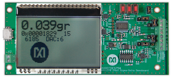
- Upon power-up, the board will take 10 measurements and display the ADC LSB value during this process. These 10 measurements will be averaged and the average will be used as the zero-position.
- The board has not been calibrated for the load cell, but the display should show ~0 grams after power-up and the numbers should change if a weight is placed at the load-cell platform. A Maxim Integrated logo should move from left to right after the first 10 measurements are taken.
- To calibrate the board, download the MAXREFDES75# calibration GUI
- Install the MAXREFDES75# calibration GUI and start it.
- Connect the micro USB cable between the PC and the MAXREFDES75#.
- The MAXREFDES75# calibration GUI displays weight history and the results on the left. On the right are two tabs for “Automatic Calibration” and “Manual Calibration.”
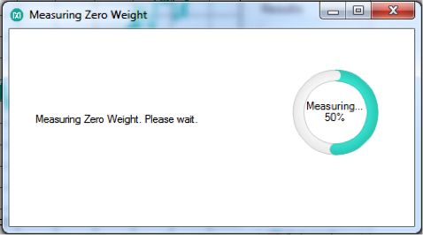
- Click the “Calibrate Weight” button, a message box opens and reminds the user to remove all weights from the platform. Vibration and any air movement should be avoided during the measurement as much as possible. Click the“OK” button.
- The MAXREFDES75# will take 10 measurements while there is no weight on the platform and shows the progress.
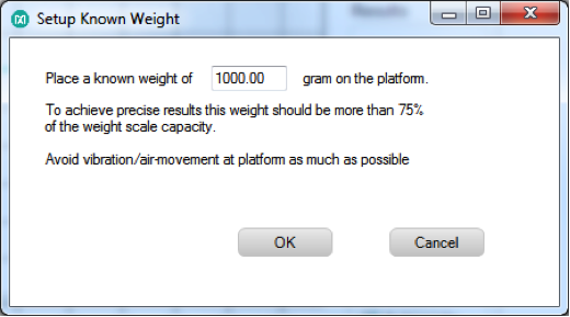
- After this, a pop-up window opens and asks the user to place a known weight on the platform and the weight in grams should be entered in the text box. After entering the weight, click the “OK” button.
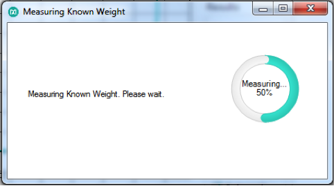
- The MAXREFDES75# will take 10 measurements while the known weight is placed on the platform and shows the progress.
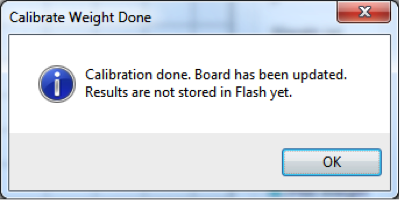
- After the second measurement, the MAXREFDES75# calibration GUI will calculate the offset and weight factor and send the results to the MAXREFDES75# board. The results are also populated in the appropriate text boxes in the “Manual Calibration” tab.
- DAC output also needs to be calibrated for the offset and gain errors.
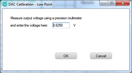
- The MAXREFDES75# will generate DC 0.625V. Measure the exact result with the multimeter and enter the measured result into the text box and click the “OK” button.
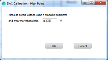
- The MAXREFDES75# will generate DC 9.375V. Measure the exact result with the multimeter and enter the measured result into the text box and click the “OK” button.
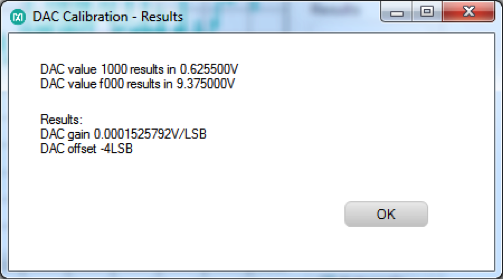
- After the second measurement, the MAXREFDES75# calibration GUI will calculate offset and gain for the analog output and will send the results to the MAXREFDES75# board. The results are also populated in the appropriate text boxes in the “Manual Calibration” tab.
- The output mapping between weight and output voltage can be calibrated as well.
- Verify that the weight scale now measures weight accurately and that the analog output changes appropriately.
- To store the calibration values to flash, click the “Save All Calibrations to Flash” button. This saves the calibration data into the MAXQ622 mounted on the MAXREFDES75#. The PC is not required for stand-alone system use after this step.
- Disconnect the USB.
- Power cycle the MAXREFDES75# and verify that the weight is measured correctly and that the analog output changes are calibrated.
Positive supply for load cell S+, negative supply for load cell S-.
Load cell output connects to IN+ and IN-.
Note: Remove all weights from the load cell prior to power-up, avoid vibrations while the first 10 measurements are taken.
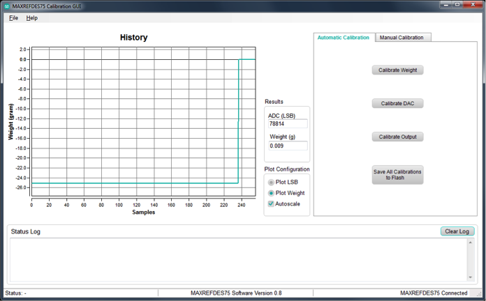
The recommended process is to use the “Automatic Calibration” tab, which leads the user through the entire process. The calibration factors established by the automatic calibration are populated in the appropriate text boxes in the “Manual Calibration” tab and can be reviewed after calibration.
Connect a precision multimeter between AOUT and AGND on the right side (if oriented such that the display can be read) of the board. Click the “Calibrate DAC” button.
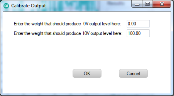
Click “Calibrate Output”.
A pop-up window asks the user to enter a weight in grams that should produce 0V output.
Note: Weights below that will also produce 0V.
And enter the weight that should produce 10V output.
Note: Weights above that will also produce 10V.
Click the “OK” button.
Stand-alone operation (after the first calibration was done)
- The weight on display shows weight in grams.
- Analog output voltage is produced based on the calibration done with the MAXREFDES75# calibration GUI.
- To reset the weight back to null, push the “S1” button (far right button if board is oriented such that the display can be read), this sets the weight back to zero.
- To reset the system, push the “S3” button (far left button if board is oriented such that the display can be read).
Windows is a registered trademark and registered service mark of Microsoft Corporation.