MAXREFDES37#:IO-LINK四通道伺服驱动器
MAXREFDES37# IO-Link®伺服驱动器提供5V电源、四路PWM输出和四路数字输入,用于控制多达四个5V伺服电机。IO-Link能够代替工业应用中的气动执行器及其压缩空气管路。增加电平转换器后,数字输入允许连接至二进制位置或状态传感器。设计开创了工业领域的崭新应用,开创新的传统气动方案。
板载标准3引脚连接头允许快速连接至常用的5V伺服电机。MAXREFDES37#附带一台HiTec HS-53伺服电机。插入式连接端子允许方便连接5V数字输入、电源、地,并操作全部四路PWM通道。可靠的外螺纹M12-4连接器允许连接任何兼容IO-Link的主机。MAXREFDES37#采用TMG TE的IO-Link设备栈。Maxim Integrated建议MAXREFDES79# IO-Link主机与图形用户界面(GUI)程序配合使用,方便使用Windows® PC进行验证。
关于实验室测量数据的更多信息,请参考详细资料标签页。包括IODD文件、原理图、PCB文件及物料单(BOM)在内的设计文件可从设计资源标签页下载。
特性
- 四路5V PWM输出
- 四路5V数字输入
- 5V/3.4A伺服电源
- 兼容IO-Link 1.1版
- IEC 61131-9
- TMG TE设备栈
- 瞬态电压抑制器(TVS)二极管满足下列保护要求:
IEC 61000-4-2 (ESD)
IEC 61000-4-4 (EFT)
竞争优势
- 全球第一款IO-Link伺服驱动器
- 四个同时工作伺服驱动器
- 不再需要气动空气管线
应用
- 控制和自动化
- 代替气动驱动


详情介绍
Introduction
Traditional pneumatic actuators have known disadvantages. Air producing equipment adds cost. Furthermore, high pressure air condenses easily, can leak and also can be very noisy. Everyone is familiar with the roar of an air compressor while putting air into a car or bike tire.
IO-Link is the first open, field bus agnostic, low-cost, point-to-point serial communication protocol, used for communicating with sensors and actuators, that has been adopted as an international standard (IEC 61131-9).1 IO-Link can directly function from the PLC or can be converted from all standard field busses to IO-Link through a gateway, quickly making it the de facto standard for universally communicating with smart sensors and actuators.
Maxim Integrated and TMG TE collaborated in designing the MAXREFDES37# version 1.1-compliant IO-Link servo driver actuator reference design. The MAXREFDES37# design consists of a Maxim Integrated IO-Link device transceiver (MAX14821), an efficient industrial step-down converter (MAX17504), and a low-power Renesas 16-bit microcontroller (RL78) utilizing TMG TE’s IO-Link device stack. Figure 1 shows the system block diagram.
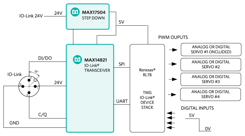 Figure 1. The MAXREFDES37# reference design block diagram.
Detailed Description of Hardware
The MAXREFDES37# IO-Link master consists of 4 main blocks: IO-Link device transceiver, step-down converter, microcontroller, and one of four possible servo motors as shown in Figure 1.
The MAX14821 IO-Link device transceiver is IO-Link version 1.1/1.0 physical layer compliant with configurable outputs (push-pull, pnp or npn), reverse-polarity/short-circuit protection, extensive fault monitoring all in a tiny 2.5mm x 2.5mm WLP package.
The MAX17504 is a high-voltage, synchronous step-down converter that efficiently converts 24V to 5V in a small 5mm x 5mm, 20-pin TQFN package. The circuit defaults to PFM operation to achieve the highest efficiency during light and heavy loads. It also implements a soft-start to limit inrush current at initial power-up and an active-low RESET output that keeps the microcontroller in reset until the output voltage is stable.
An ultra-low-power RL78/G13 microcontroller with current consumption down to 66µA/MHz provides system control. It features 512kB of flash ROM, 8kB of data flash, 32kB of on-chip RAM, and uses a 5V supply in a HWQFN 7mm x 7mm package.
Transient voltage suppressor (TVS) diodes are not all equal. The SDC36 TVS diodes have a clamping voltage less than 55V and meet both IEC 61000-4-2 (ESD) and IEC 61000-4-4 (EFT). There are many smaller TVS diodes on the market that cannot meet these specifications.
The MAXREFDES37# ships with a HiTec HS-53 servo motor and easily plugs into the onboard standard 3-pin headers as shown in Figure 2.
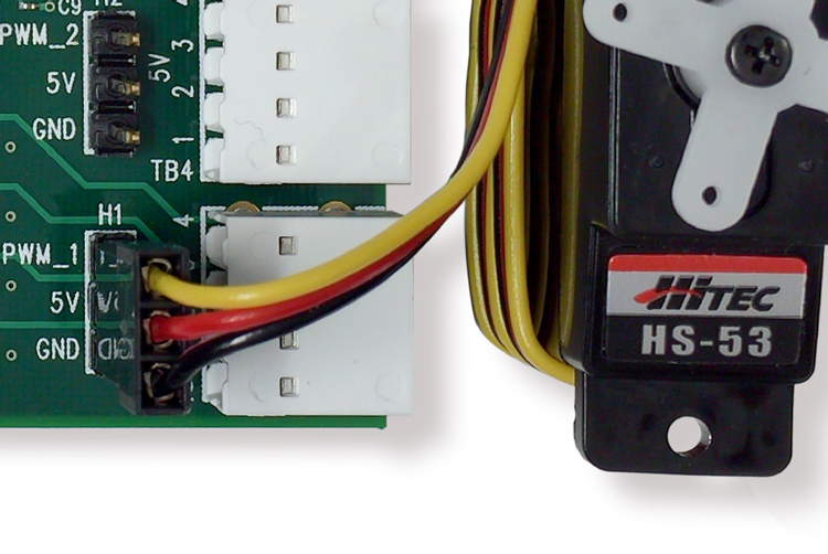 Figure 2. HiTec HS-53 servo motor connected to the standard 3-pin header on the MAXREFDES37# reference design.
Description of Software
TEConcept CT Windows-compatible GUI software features IODD file import capability, connects to a PC via USB, and is available to download from the Design Resources tab of the MAXREFDES79# webpage. The TEConcept CT software is shown in Figure 3 and a complete step-by-step Quick Start guide is also downloadable from the Design Resources tab of MAXREFDES79#.
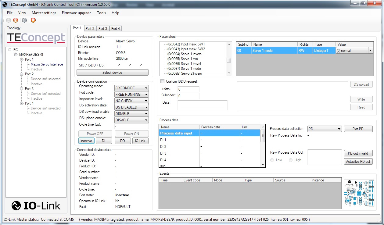 Figure 3. MAXREFDES37# TEConcept CT tool.
Detailed Description of Firmware
The MAXREFDES37# ships pre-programmed as a working IO-Link servo driver ready to connect to an IO-Link master. The firmware targets a Renesas RL78 microcontroller and follows the simple flowchart shown in Figure 4. The firmware is written in C using the IAR embedded workbench from IAR Systems and utilizes TMG TE’s IO-Link device stack.
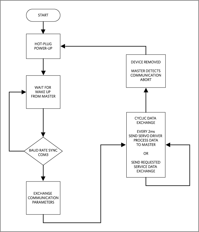 Figure 4. The MAXREFDES37# firmware flowchart.
After hot plug-in, the MAXREFDES37# waits for a wake-up signal from the IO-Link master. After receiving the wake-up signal, the MAXREFDES37# synchronizes to the IO-Link master’s 230.4kbps baud rate (COM3). Communication parameters are exchanged. The MAXREFDES37# then starts a cyclic data exchange every 2ms by sending the sensor process data to the IO-Link master. If the sensor is removed, the IO-Link master will detect a missing sensor.
Detailed Description of Use Cases
There are two different use cases that you should consider before purchasing MAXREFDES37#. Use case 1 is simply using the MAXREFDES37#, which is preprogrammed to connect with a user-supplied IO-Link master and IO-Link cable as shown in Figure 5. Use case 2 is where the entire firmware development system is needed as shown in Figure 6.
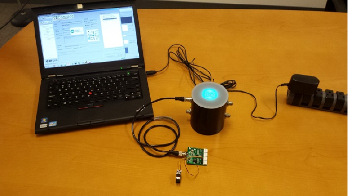 Figure 5. Use case 1 is the MAXREFDES37# quick start system.
Table 1. Recommended Components Needed for Use Case 1
| Use Case 1 (MAXREFDES37# Quick Start System) | ||
|---|---|---|
| Company | Description | Orderable Part Number |
| Maxim Integrated | IO-Link Servo Driver (ships programmed) Includes: HiTec HS-53 Servo Motor |
MAXREFDES37# |
| Maxim Integrated | USB IO-Link Master (ships with 2 IO-Link Cables) |
MAXREFDES79# |
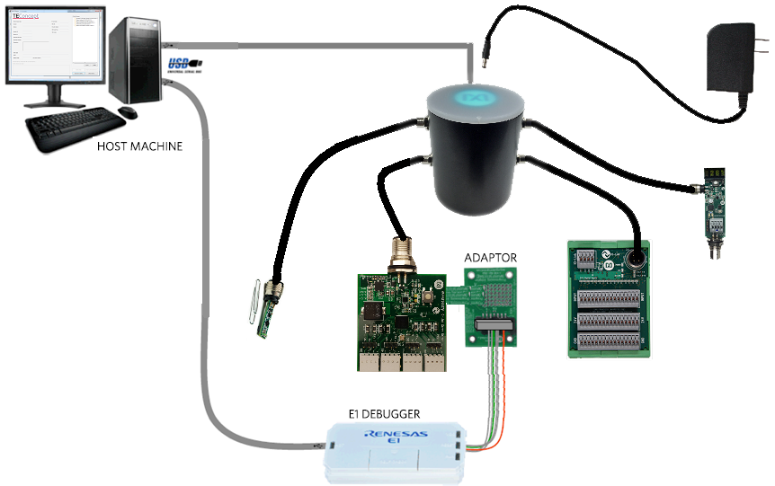 Figure 6. Use case 2 is the MAXREFDES37# firmware development system.
Table 2. Recommended Components Needed for Use Case 2
| Use Case 2 (RL78/G13 development system—Renesas Starter Kit for RL78/G13) | ||
|---|---|---|
| Company | Description | Orderable Part Number |
| Renesas Electronics | Renesas Starter Kit for RL78/G13 Includes: IAR Embedded Workbench for Renesas RL78 E1 Programmer/Debugger |
YR0K50100LS000BE |
| Maxim Integrated | IO-Link Servo Driver (ships programmed) Includes: HiTec HS-53 Servo Motor |
MAXREFDES37# |
| Maxim Integrated | USB IO-Link Master (ships with 2 IO-Link Cables) |
MAXREFDES79# |
| Maxim Integrated | E1 to MAXREFDES37# adaptor board. | MAXREFDES23DB# |
Contact Renesas Electronics for more information or questions regarding the RL78/G13.
Quick Start
Required Equipment:
Purchased from Maxim Integrated:
- MAXREFDES37# (box contents)
- MAXREFDES37# board (see Note 1)
- HiTec HS-53
User-supplied:
- Windows 7 or Windows 8 PC with a USB port
- MAXREFDES79# USB IO-Link Master (see Note 1)
Note 1: Download files from the Design Resources tab for the MAXREFDES37# or MAXREFDES79#
Download, read, and carefully follow each step in the appropriate MAXREFDES37# Quick Start Guide.
Lab Measurements
Equipment used: Exactly the same equipment that was used in the MAXREFDES37# Quick Start.
Figure 7 shows a screenshot of the MAXREFDES37#’s PWM signal driving the HiTec HS-53 servo motor to 0 degrees. Figure 8 a screenshot of the MAXREFDES37#’s PWM signal driving the HiTec HS-53 servo motor to 90 degrees. Figure 9 shows a screenshot of the 20ms period of the MAXREFDES37#’s PWM signal. Figure 10 shows a graph of the MAXREFDES37#’s 24V line current versus different dynamic servo drive modes and numbers of servo motors.
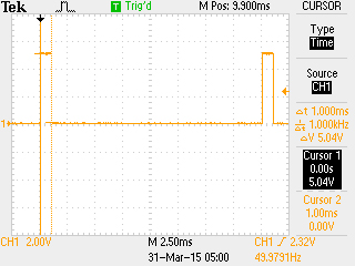 Figure 7. Screenshot of MAXREFDES37# PWM signal driving a HiTec HS-53 servo motor to 0 degrees (1ms PWM high time) using process data out servo 1 value of -100 and servo 1 travel parameter of 1000.
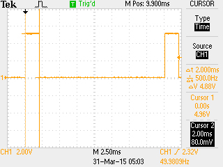 Figure 8. Screenshot of MAXREFDES37# PWM signal driving a HiTec HS-53 servo motor to 90 degrees (2ms PWM high time) using process data out servo 1 value of 100 and servo 1 travel parameter of 1000.
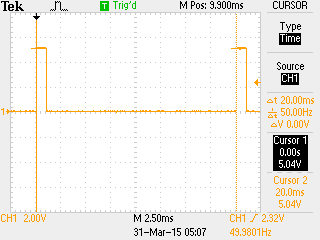 Figure 9. Screenshot of 20ms period of the MAXREFDES37# PWM signal.
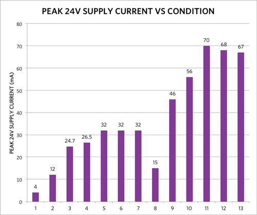 Figure 10. MAXREFDES37# 24V line current vs. various condition and amount of servo motors at room temperature (Table 3).
Table 3. Measurement Conditions for Figure 10.
| Number | 24V Peak Current (mA) | Condition Global: MAX17504 = PFM mode |
|---|---|---|
| 1 | 4 | invert 0, trim 0, travel 1000, mode = normal, no servos connected, IO-Link connected |
| 2 | 12 | invert 0, trim 0, travel 1000, mode = normal = servo not moving, only 1 HS-53 connected to H1 |
| 3 | 24.7 | invert 0, trim 0, travel 1000, mode = (1) triangle slow, only 1 HS-53 connected to H1 |
| 4 | 26.5 | invert 0, trim 0, travel 1000, mode = (2) triangle fast, only 1 HS-53 connected to H1 |
| 5 | 32 | invert 0, trim 0, travel 1000, mode = (3) rectangle, only 1 HS-53 connected to H1 |
| 6 | 32 | invert 0, trim 0, travel 1000, mode = (4) sawtooth rising, only 1 HS-53 connected to H1 |
| 7 | 32 | invert 0, trim 0, travel 1000, mode = (5) sawtooth falling, only 1 HS-53 connected to H1 |
| 8 | 15 | invert 0, trim 0, travel 1000, mode = (0) normal (not moving), 1 HS-53 connected to H1, 1 HS-53 connected to H2 |
| 9 | 46 | invert 0, trim 0, travel 1000, mode = (1) triangle slow, 1 HS-53 connected to H1, 1 HS-53 connected to H2 (both servos running same mode) |
| 10 | 56 | invert 0, trim 0, travel 1000, mode = (2) triangle fast, 1 HS-53 connected to H1, 1 HS-53 connected to H2 (both servos running same mode) |
| 11 | 70 | invert 0, trim 0, travel 1000, mode = (3) rectangle, 1 HS-53 connected to H1, 1 HS-53 connected to H2 (both servos running same mode) |
| 12 | 68 | invert 0, trim 0, travel 1000, mode = (4) sawtooth rising, 1 HS-53 connected to H1, 1 HS-53 connected to H2 (both servos running same mode) |
| 13 | 67 | invert 0, trim 0, travel 1000, mode = (5) sawtooth falling, 1 HS-53 connected to H1, 1 HS-53 connected to H2 (both servos running same mode) |
References
- IO-Link System Description 2013 by IO-Link Company Community. Page 3, Preface.
IO-Link is a registered trademark of ifm electronic GmbH.
Windows is a registered trademark and registered service mark of Microsoft Corp.
Renesas is a registered trademark and registered service mark of Renesas Electronics Corporation.