MAXREFDES89#:MAX14871全桥直流电机驱动器MBED平台
MAXREFDES89#为开发有刷直流电机提供理想接口。设计为mbed®兼容,Arduino®架构平台,用于快速开发有刷直流电机的应用。平台包括四片MAX14871全桥直流电机驱动器,可驱动最多4个电机。MAX17501 DC-DC转换器让系统可工作在一个7V至36V直流的单电源。四片MAX4704 4:1多路复用器允许设置MAX14871的电流调节模式,同时两片MAX5387数字电位计,提供了可以设置电机限流值。MAX7300 GPIO扩展器支持将每个电机驱动器电路连接至支持mbed的微控制器平台。
以下链接提供了支持平台的mbed库文件:MAX14871_Shield Library。库文件概括了连接参考设计的支持硬件的接口详情,使用户能够专注于其应用。
MAXREFDES89#是快速开发工具,使用户在开发应用期间具有最大的灵活性。最终设计中,MAX14871可能是驱动有刷直流电机以及调节电机电流所需的唯一器件。
关键特性
- 7V至36V电源电压范围
- 板载DC-DC转换器,为mbed电路板提供VIN
- 提供mbed库文件
- 2A (最大值)电流调节限值/电机驱动器
- 提供四片电机驱动器
- Arduino平台规格
竞争优势
- 安全:25%纹波电流调节;灵活:较宽电源电压范围
- 低RON节省功耗
- 可靠:GND/VCC短路保护
应用
- 工业自动化
- 打印机扫描仪
- 自动售货机和游戏机
- 机器人


详情介绍
Introduction
Brushed DC motors provide cost-effective, convenient motion in many applications ranging from electric toothbrushes to vending machines. The simplicity and reliability of brushed DC motors also make them ideal for prototyping and hobbyist designs. Now, the MAXREFDES89# provides developers with a rapid prototyping and development platform for driving brushed DC motors.
The MAXREFDES89# is an mbed-compatible, Arduino form factor shield for the rapid production of brushed DC motor applications. The shield contains four MAX14871 full-bridge DC motor drivers, one MAX17501 DC-DC converter, four MAX4704 4:1 multiplexers, two MAX5387 digi pots and one MAX7300. Each MAX14871 provides the necessary functions to drive a brushed DC motor, while the additional parts allow for complete testing and operation in a variety of configurations.
The MAXREFDES89# is a tool for rapid development that offers optimal flexibility to the user during development of their application. In a final design, the only required silicon for driving a brushed DC motor and regulating the motor’s current is the MAX14871.
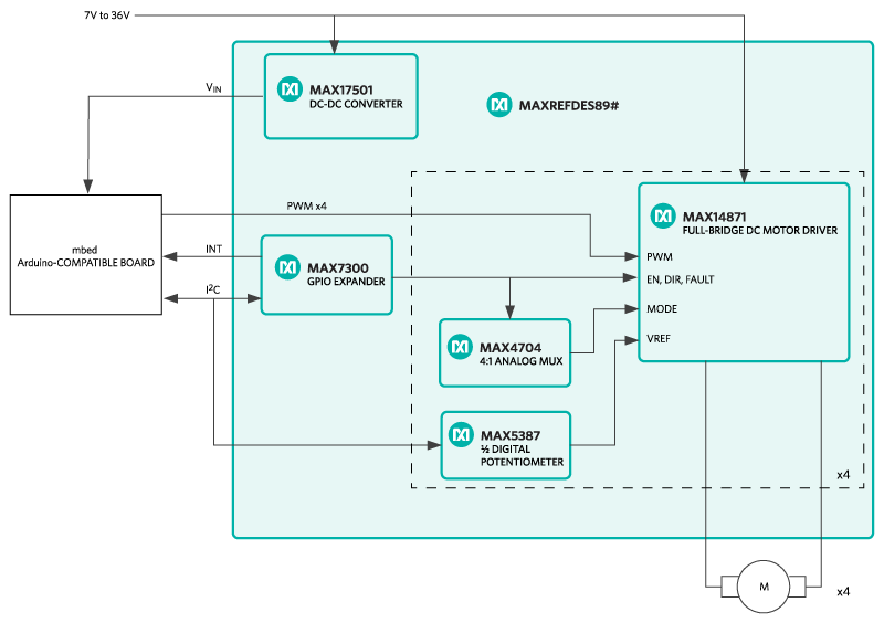 Figure 1. MAXREFDES89# block diagram.
Detailed Description of Hardware
Please see Figure 1 for a block diagram of the MAXREFDES89#.
Please refer to the MAXREFDES89# schematic sheet 1 of 6 for the following discussion.
The supply voltage range for the MAXREFDES89# is 7V to 36V DC. The required current depends on the motors used, which can have a continuous current of up to 2A per driver. The shield contains a MAX17501 DC-DC converter which provides a 5.7V typical VIN to the mbed platform via Schottky diode D2.
The MAX17501 offers an active-low RESET output which will reset the mbed platform on an undervoltage condition of ~6.98V at VBAT if JP1 is removed. This feature can be disabled by installing JP1 on pins 1 and 2. The mbed board can be isolated from the active-low RESET output of the MAX17501 by removing R67.
The direct interfaces between the mbed platform and the shield are the following:
- I2C bus on D14 and D15 (SDA and SCL, respectively)
- PWM channels on D4, D5, D9, and D10 default locations (configurable to D3, D6, D8, and D11 via 0Ω resistors. If D11 is used, the use of the SPI bus that typically is available on mbed platforms becomes unavailable).
- Interrupt in from the MAX7300 GPIO expander on D2 (configurable to D7 via 220Ω resistor).
Please see Table 1 for configurable interface options.
Table 1. Interface Options
| Interface | Default | Optional | Resistors (Default/Optional) |
|---|---|---|---|
| Active-Low RESET | Installed | Removed | R67 |
| MD1_PWM | D4 | D3 | R11/R12 |
| MD2_PWM | D5 | D6 | R10/R9 |
| MD3_PWM | D9 | D8 | R7/R8 |
| MD4_PWM | D10 | D11 | R6/R5 |
| MDX_INT | D2 | D7 | R24/R66 |
Refer to the MAXREFDES89# schematic sheet 2 of 6 for the following discussion.
There is an option to stack up two MAXREFDES89# shields for applications that require the control of up to eight motors. To support this feature, the mbed platform must support PWM on the required channels. The FRDM-KL25Z has been tested and supports all eight possible drivers. No more than two MAXREFDES89# shields can be stacked.
Additionally, the I2C addresses of the MAX7300 GPIO expander and the MAX5387 digi pot will need to be changed. For the optional positions, please see Table 2. For the simplest operation when stacking two boards, move all configuration resistors to their optional positions on one board, and leave the resistors in their default positions on the other board. The mbed library supports two configurations, the default configuration and the optional configuration. Other configurations can be used of course; however, this will require the user to edit the library for their configuration.
Table 2. I2C 7-Bit Slave Addresses
| Device | Default Address | Optional Address | Resistors (Default/Optional) |
|---|---|---|---|
| MAX7300 U2 | 0x40 | 0x41 | R22/R21 |
| MAX5387 U3 | 0x28 | 0x30 | R14/R13 |
| MAX5387 U4 | 0x29 | 0x31 | R18/R17 |
Refer to the MAXREFDES89# schematic sheet 3 through 6 for the following discussion.
The MAX7300 GPIO expander provides many GPIOs in the system. The user has control of the active-low EN and DIR pins of each MAX14871 motor driver. The MAX7300 also controls the ADDA and ADDB pin of each MAX4704, a 4:1 analog multiplexer (U5, U7, U9, U11), which sets the voltage on the MODE pin of each MAX14871 (U6, U8, U10, U12). The voltage on the MODE pin of a MAX14871 sets the current regulation mode of the device. One half of each MAX5387 digital potentiometer (U3, U4), is used to set the voltage reference, VREF, on the corresponding MAX14871 for the external current regulation limit.
Detailed Description of Firmware
The MAXREFDES89# must be used with an ARM® mbed-compatible platform, for application development. To accelerate development with the MAXREFDES89#, the mbed MAX14871_Shield Library was developed along with a simple terminal demo program which demonstrates the use of the library and the features of the shield.
Figure 2 provides a high-level flow chart of the program and documentation of the MAX14871_Shield Library can be found in the design files.
 Figure 2. Demo program flowchart.
Quick Start
Required equipment
- Windows® PC with a USB port
- MAXREFDES89#
- Compatible Arduino form factor mbed platform
- One to four brushed DC motors
- Suitable power supply for motors, 7V to 36V
Procedure
The reference design is fully assembled and tested. Follow the steps below to verify board operation.
- Connect MAXREFDES89# to mbed platform.
- Connect the power supply to MAXREFDES89# P1. Observe polarity.
- Connect motor to one of the four available motor driver outputs (P6-P9, P6 corresponds to MD1).
- Connect USB cable from the PC to the mbed platform SDA USB port.
- Import the demo from the following link, demo program, to your mbed compiler.
- Compile and download the resulting binary to your mbed platform.
- Open Hyperterminal, or your favorite terminal emulator, find the appropriate COM port for your mbed platform, and configure the connection for 9600bps, 8-N-1 with no flow control.
- Press the reset button on the MAXREFDES89# and exercise the demo.
The output of motor driver 1 is P6, motor driver 2 is P7, etc.
Lab Measurements
Equipment used
- Tektronix TDS3014 Oscilloscope
- Tektronix TCP202 Current Probe
- MAXREFDES89#
- FRDM-KL25Z
- PMDC Motor
- Windows PC with a USB port to exercise demo for measurements.
Figure 3, Figure 4, and Figure 5 show the 25% ripple current regulation mode of the MAX14871 motor driver at startup and steady-state operation. In each measurement channel 1 is the PWM signal to the motor driver, channel M is the math function and the difference between channels 2 and 3 (M1 and M2 of the motor driver), and channel 4 is the motor current measured with a current probe. Each measurement was triggered off of the first rising edge of the PWM signal. All of the measurements used the typical internal voltage reference of 1V, current-sense amplifier gain of 10V/V, and a sense resistor of 100mΩ. This configuration results in a current limit, Ilim, of 1A.
In Figure 3, the motor armature current was 0A prior to the rising edge of the PWM signal and the motor was at rest. On the rising edge of the PWM signal, the armature current begins to rise with the motor's L/R time constant. During this time, the motor driver operates in normal PWM operation as shown on page 9 of the MAX14871 data sheet, where the duty cycle of the PWM signal directly controls the average voltage at the motor terminals.
Once the armature current reaches Ilim the motor driver begins to operate in the current regulation mode, 25% ripple. For this mode of current regulation, the motor terminal voltage is reversed, therefore reversing the change in armature current, until the armature current is reduced to Ilim - Ilim × 0.25. Once the armature current is reduced to within 25% of Ilim, the motor terminal voltage is reversed back to the original polarity. This "back and forth" process continues as long as the armature current continues to rise to Ilim, and produces a 25% ripple armature current regulated to within Ilim and (Ilim - 0.25 × Ilim).
By regulating the motor armature current during startup, or a load transient, a smaller power supply can be used to power the motor. Additionally, the 25% ripple current regulation mode can be used for a broad range of motors and the time constant of the motor does not need to be considered as with the fixed off-time modes of regulation.
In Figure 4, the motor armature current prior to the first rising edge of the PWM signal was 0A. The current regulation and Ilim are the same as Figure 3, however, the PWM signal now has a duty cycle of 50% instead of 100%. Notice, prior to the armature current reaching Ilim, at approximately 260µs, the duty cycle of the PWM signal directly controls the average voltage at the motor terminals. Once the armature current reaches Ilim, the same current regulation process, as described in Figure 3, takes place during the positive duty cycle of the PWM signal. When the PWM signal is low, the motor voltage is forced to 0V.
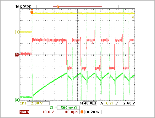 Figure 3. 25% current regulation mode during startup and 100% PWM duty cycle.
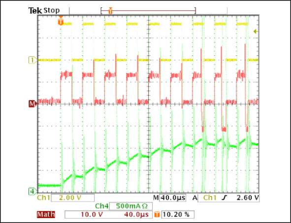 Figure 4. 25% current regulation mode during startup and 50% PWM duty cycle.
Figure 5 shows the same measurement as Figure 3, however the time base is 40ms, to show the steady-state motor armature current. Note how the PWM duty cycle directly controls the average voltage at the motor terminals once the motor armature current decreases below Ilim, this is normal PWM operation.
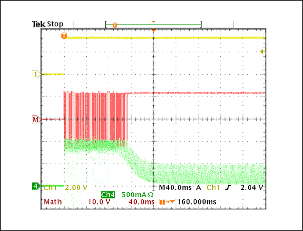 Figure 5. 25% current regulation mode during startup and steady-state continuous motor current, 100% duty cycle.
The other two modes of current regulation offered by the MAX14871 are Fixed Off-Time Regulation with Fast Decay and Slow Decay. The Fixed Off-Time with Fast Decay mode allows an external capacitor to set a fixed time that the motor terminal voltage is reversed. In this case, the motor’s time constant must be taken into consideration. When using the Fixed Off-Time with Slow Decay, the motor terminal voltage is set to 0V instead of being reversed.
Figure 6, Figure 7, Figure 8, Figure 9, Figure 10, and Figure 11 show the same measurements as Figures 3 to 5 do for Fixed Off-Time with Fast Decay and Fixed Off-Time with Slow Decay, respectively.
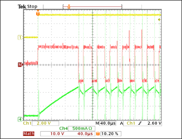 Figure 6. Fixed-off time with fast decay current regulation during startup with 100% duty cycle.
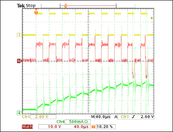 Figure 7. Fixed-off time with fast decay current regulation during startup with 50% duty cycle.
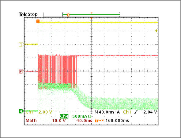 Figure 8. Fixed-off time with fast decay current regulation during startup with 100% duty cycle.
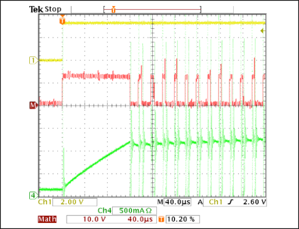 Figure 9. Fixed-off time with slow decay current regulation during startup with 100% duty cycle.
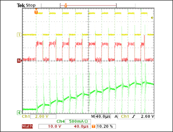 Figure 10. Fixed-off time with slow decay current regulation during startup with 50% duty cycle.
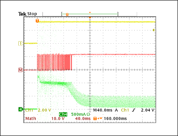 Figure 11. Fixed-off time with slow decay current regulation during startup with 100% duty cycle.