Intelligent Lighting Controller Measures Ambient Light and Tracks Time
Add Digital Brains to a Basic Luminaire
Outdoor lighting is usually switched on or off manually with a mechanical switch. Suppose, however, that you do not want to illuminate an area for the whole night. In that case, it would be advantageous to control the illumination more precisely so you can automatically switch the lighting off/on at a prescribed time.
A controller can sense ambient light, turn lights on when it gets dark, track a time interval, and automatically turn the lights off at a specified time. In the morning, the process can be reversed. If the ambient light level is under a preset lux threshold at a predetermined time, the system will turn on the light. It will turn the light off when the ambient gets bright enough to surpass the same lux threshold.
It is not difficult to design an intelligent lighting controller that senses and measures the ambient light level with an ambient light sensor (ALS). Equipped with a real-time clock (RTC), the controller also knows when to turn lighting on or off at specified times. The system presented here can be used to control all luminaires that are mains supply operated. The controller's lux-level threshold is fully programmable in single-lux steps. Controller software is provided in hex format.
Integral System Components
The lighting controller in this design needs to measure the ambient light level, which is done with an ALS. There are two different kinds of ALS products in the market today: one outputs the analog voltage proportional to the ambient light level, and the other gives the output in digital format. This system uses the ALS with the digital output.
The controller needs to know the exact time, so a real-time clock (RTC) is used. To anticipate possible power loss, the time information needs battery backup.
A user interface is needed for setting time and other parameters. The user interface here consists of two 7-segment LED displays and one pushbutton. With a short button press, the system displays time and other parameters. With a long button press, the time and parameters can be adjusted.
The system has an auto/manual switch to enable switching the light on or off manually.
System power comes from the mains supply. Electricity to the luminaire is switched on/off through a relay. The digital portion of the system is isolated from mains supply.
The system block diagram is shown in Figure 1.
Figure 1. Lighting controller system.
Figure 2 further illustrates the system wiring to the mains supply voltage and to luminaire(s).
Figure 2. System wiring to the mains supply voltage and to luminaire(s).
When the system is used in manual mode, the auto/manual switch must be switched to manual. In manual mode, the relay is continuously on and the luminaires are switched on/off using a standard wall light switch.
When the auto/manual switch is in auto mode, the standard wall light switch must be switched on so the controller can function. If that wall switch is not on, the controller cannot switch the luminaires on.
One system can contain multiple luminaires.
详情介绍
Add Digital Brains to a Basic Luminaire
Outdoor lighting is usually switched on or off manually with a mechanical switch. Suppose, however, that you do not want to illuminate an area for the whole night. In that case, it would be advantageous to control the illumination more precisely so you can automatically switch the lighting off/on at a prescribed time.
A controller can sense ambient light, turn lights on when it gets dark, track a time interval, and automatically turn the lights off at a specified time. In the morning, the process can be reversed. If the ambient light level is under a preset lux threshold at a predetermined time, the system will turn on the light. It will turn the light off when the ambient gets bright enough to surpass the same lux threshold.
It is not difficult to design an intelligent lighting controller that senses and measures the ambient light level with an ambient light sensor (ALS). Equipped with a real-time clock (RTC), the controller also knows when to turn lighting on or off at specified times. The system presented here can be used to control all luminaires that are mains supply operated. The controller's lux-level threshold is fully programmable in single-lux steps. Controller software is provided in hex format.
Integral System Components
The lighting controller in this design needs to measure the ambient light level, which is done with an ALS. There are two different kinds of ALS products in the market today: one outputs the analog voltage proportional to the ambient light level, and the other gives the output in digital format. This system uses the ALS with the digital output.
The controller needs to know the exact time, so a real-time clock (RTC) is used. To anticipate possible power loss, the time information needs battery backup.
A user interface is needed for setting time and other parameters. The user interface here consists of two 7-segment LED displays and one pushbutton. With a short button press, the system displays time and other parameters. With a long button press, the time and parameters can be adjusted.
The system has an auto/manual switch to enable switching the light on or off manually.
System power comes from the mains supply. Electricity to the luminaire is switched on/off through a relay. The digital portion of the system is isolated from mains supply.
The system block diagram is shown in Figure 1.
Figure 1. Lighting controller system.
Figure 2 further illustrates the system wiring to the mains supply voltage and to luminaire(s).
Figure 2. System wiring to the mains supply voltage and to luminaire(s).
When the system is used in manual mode, the auto/manual switch must be switched to manual. In manual mode, the relay is continuously on and the luminaires are switched on/off using a standard wall light switch.
When the auto/manual switch is in auto mode, the standard wall light switch must be switched on so the controller can function. If that wall switch is not on, the controller cannot switch the luminaires on.
One system can contain multiple luminaires.
System Description
The system schematic is shown in Figure 3.
More detailed image (PDF, 230kB)
Figure 3. System schematic.
Selecting the Essential Components
The mains voltage is transformed to 9VAC (RMS). Only one voltage rail (3.3V) is used in this system, so power conversion is easy and straightforward. The transformer secondary-side voltage is regulated to 3.3V using the MAX16910 LDO. This LDO was chosen because it has built-in short-circuit and thermal protection. Fuse F1 is a 500mA PTC Polyswitch®, used for additional protection.
The system microcontroller is the Microchip® PIC18LF4520 running at a 8MHz clock frequency. The microcontroller's clock is the MAX7375, a very small (SC-70) silicon oscillator, chosen because it has an excellent temperature coefficient and very little jitter.
The RTC is the DS1340C. This clock has a built-in oscillator so it consumes ultra-low power when the supply comes from a backup power source. The DS1340C is interfaced with an I²C bus. It also has a built-in trickle charger. Therefore, if a rechargeable battery or capacitor is used as the backup power source, it is always fully charged by the DS1340C.
The backup power source, BT1, is a 0.47mF memory-storing capacitor. In the event of a power loss, BT1 will feed power to the DS1340C RTC. When this RTC is supplied from a backup source, it consumes only 1µA (max) current. With the 0.47mF capacitor and with a 3.3V capacitor voltage, the RTC will keep timing information for approximately 36 hours. If the backup time needs to be longer than that, the memory-storing capacitor can be replaced with two series-connected AA batteries. This will lengthen the operating time from 36 hours up to several months. Note, however, that now the DS1340C's built-in trickle charger needs to be disabled by writing 0x00h to the DS1340C's register 08h.
The user interface is very simple: one pushbutton and two 7-segment LED displays. The displays are driven by theMAX6958 LED display driver and are interfaced with I²C, as are the ALS and RTC.
The ALS (Figure 4) is not mounted on the controller's PCB, but inside the luminaire chassis. The sensor is connected to the PCB with a 4-wire cable using connector J1. This ALS is the MAX44009, chosen because it comes in an ultra-small (2mm x 2mm), 6-pin UTDFN package that fits easily inside the luminaire chassis (Figure 5).
Figure 4. Schematic for the MAX44009 ALS.
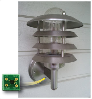
Figure 5. Ambient light sensor PCB (picture on the left) is mounted inside the luminaire chassis (small black dot visible at the bottom of the chassis). Luminaire photo courtesy of Marko Kannisto.
Other General Design Parameters
The luminaire supply is controlled by a relay with transistor T1 because of a 12V relay coil voltage. Connector J2 is used to program and debug the microcontroller. There are also 4 indicator LEDs: power on (V_ON); system running (OK); and hour (HR) or minute (MIN) displayed on 7-segment displays with DS1 and DS2.
Positioning the ALS
Sensor placement is critical for good operation. A small hole is drilled in the luminaire chassis and is sealed with transparent tape. The ALS's PCB is placed in the middle of the hole so the sensor "sees" and measures the ambient light level. The sensor PCB is attached to the luminaire chassis using hot glue.
Placement of the ALS should be considered carefully. If the sensor "sees" the light from the luminaire itself, it cannot measure the ambient light level correctly in the morning. This can cause the luminaire to blink on and off continuously.
At the evening, however, this ALS positioning is not an issue since the light is then switched off based on time, not based on the ambient light level.
Finally, it is almost impossible to place the ALS where it would not sense any light from the luminaire itself. For this reason, the luminaire's switch-off lux threshold in the morning is automatically set at greater than 8 lux in the software. This compensation only ensures that the luminaire's switch on/off happens at approximately the same ambient light level. This does not eliminate the possibility of the luminaire blinking.
System Printed Circuit Boards (PCBs)
The controller PCB top-side and bottom-side layers are shown in Figures 6 to 8.
Figure 6. Controller PCB part placement.
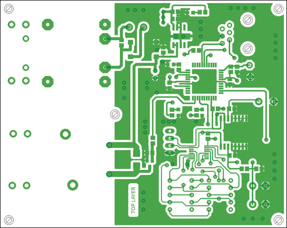
Figure 7. Controller PCB top-side layer.
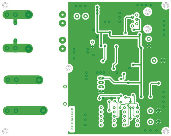
Figure 8. Controller PCB bottom-side layer.
The MAX44009 ALS is mounted on its own PCB. Its PCB part placement, top-side and bottom-side layers, are shown inFigures 9 and 10.

Figure 9. ALS PCB top-side layer.

Figure 10. ALS PCB bottom-side layer.
The ALS is connected to the controller's PCB with connector J1.
System Part Lists
The controller PCB and ALS PCB part lists are shown in Table 1 and Table 2.
| Table 1. Controller PCB Part List | |||
| Part Name | Value | Package | Description |
|---|---|---|---|
| BR1 | B40S | B40S SMD | Bridge rectifier |
| BT1 | 47mF capacitor | Pitch = 5.5mm | Memory backup capacitor |
| C1 | 1nF/50V | 0805 | Capacitor |
| C2 | 2.2nF/400V ~ X1 | Pitch = 10mm | X-capacitor |
| C3 | 10nF/50V | 0805 | Capacitor |
| C4–C8 | 100nF/50V | 0805 | Capacitor |
| C9–C11 | 10uF/50V | 0805 | Capacitor |
| C12 | 100uF/25V | Pitch = 2.54mm | Electrolytic capacitor, 6mm diameter |
| D1 | 10BQ100 | SMB | Schottky diode 1A/100V |
| D2 | Green LED | 0805 | LED |
| DS1–DS2 | SC39-11SRWA | 10 x 13mm | Common cathode, 7-segment display |
| F1 | RXEF050 | Pitch = 5mm | 500mA PTC, Polyswitch |
| HR | Green LED | 0805 | Light Emitting Diode |
| J1 | 22-23-2041 | 2.54mm pitch | Molex® 4-pin header connector |
| J2 | 520258-3 | 6-pin modular | Amp modular connector |
| J3–J6 | 6.3mm | Abiko connector | PCB through-hole tab connector |
| K1 | G8P-1A4P-12V | JT1A-PCB | OMRON® relay 12V coil voltage/30A |
| MIN | Green LED | 0805 | LED |
| OK | Green LED | 0805 | LED |
| R1–R4 | 330R | 0805 | Resistor |
| R5 | 2k2 | 0805 | Resistor |
| R6–R7 | 4k7 | 0805 | Resistor |
| R8–R11 | 10k | 0805 | Resistor |
| SET | B3F-1000 | 6mm x 6mm | PCB through-hole tactile switch |
| T1 | BC817 | SOT-23 | NPN transistor |
| TR1 | BVEI 305 2879 | EI30-1 | 230VAC to 9VAC transformer |
| U1 | MAX16910CASA8/V+ | SO-8 | Maxim linear voltage regulator |
| U2 | DS1340C-33# | SO16L | Maxim RTC |
| U3 | MAX7375AXR805+ | SC70 | Maxim 8MHz silicon oscillator |
| U4 | MAX6958AAEE+ | TSSOP16 | Maxim 7-segment LED driver |
| U5 | PIC18LF4520-I/PT | TQFP44 | Microchip microcontroller |
| Table 2. ALS PCB Part List | |||
| Part Name | Value | Package | Description |
|---|---|---|---|
| C1 | 100nF/50V | 0603 | Capacitor |
| U1 | MAX44009EDT+ | UTFDN-6 | Maxim ALS |
Using the System
The system is shown mounted into an enclosure in Figure 11.
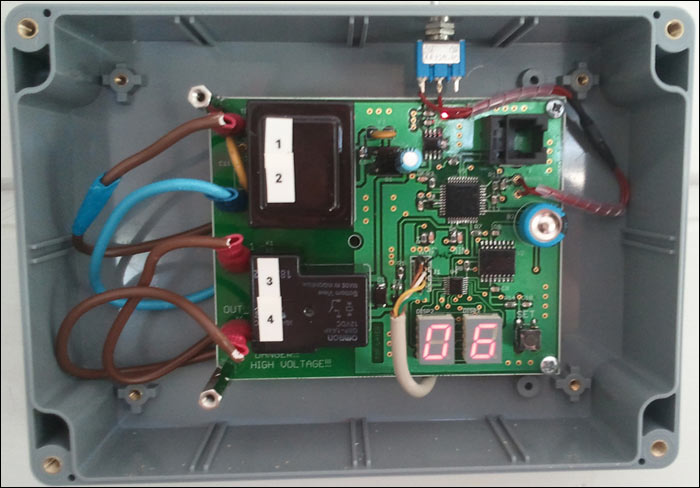
Figure 11. System mounted into enclosure. Photo courtesy of Marko Kannisto.
Using the system is fairly simple. With the SET button, a user can define these parameters in following order:
- Current hour and minute
- Ambient light lux-level threshold (default is 2 lux)
- Light turn-off time at the evening
- Light turn-on time in the morning
The turn off/on times in the evening and in the morning do not have to be set. If not set, then the luminaire will be switched on when ambient light crosses the preset lux-level threshold at dark; it will be switched off when ambient light rises above that threshold. In this mode, the time information from the RTC is not processed.
Programmed information can be read by pressing the SET button for less than 1 second. The system will then display the hour, minute, ambient lux-level threshold, light turn-off time, and light turn-on time in that order.
If a user wants to change the programmed parameters or wants to adjust the time, then press the SET button for longer than 2s. Parameters can then be set one at a time in the same order as above. When a parameter is to be programmed, press the SET button longer than 2s so the parameter can be recorded. Same procedure is done for all parameters.
When all parameters are programmed, the system will show them one at a time so the user can verify that everything is stored correctly.
Software Block Diagram
The software block diagram is shown in Figure 12.
Figure 12. Software block diagram.
The flowchart for the software is complex. The software is making numerous decisions based on time of the day (evening/morning) and the programmed parameters. Those decisions are reviewed approximately every 5 seconds.
The lux threshold that is stored needs to be crossed five times in a row with 5s intervals to switch light on or off. Or restated, the threshold must be crossed for approximately 25 seconds to switch light on or off.
Summary
With modern semiconductor technology, it is not difficult to design a controller that measures the ambient light level and controls lighting in a preset way. This application note explains how to design an intelligent lighting controller that switches a light on/off based on ambient light and time information. This system can be used to control all luminaires that are mains-supply operated.
Molex is a registered trademark of Molex Incorporated.
OMRON is a registered trademark of OMRON Corporation.
PolySwitch is a registered trademark of Tyco Electronics Corporation.